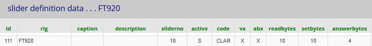
5.10 Yaesu FT920 Clarifier tuning - slider example
The sliders table data is shown below - split into two parts because of its length.
( The sliders table contains client and server data
.... whereas for buttons, they are separate in buttons and catcodes)

Setting the clarifier offset by slider positioning
The clarifier setting commands are illustrated If P1 = FF, then P2, P3 and P4 control the slider. |
|
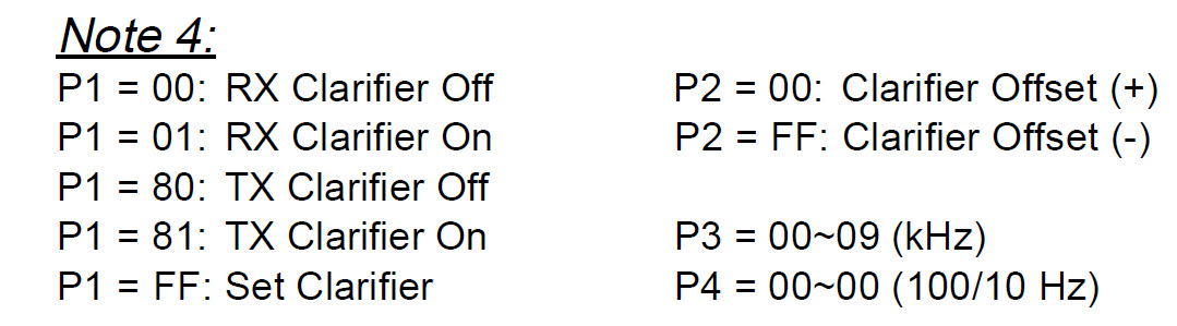
P2 is FF for a negative offset and 00 for a positive offset. P3 and P4 are the frequency in Hz x10.
eg: to set - 5.230 kHz, the command would be in BCD (binary coded decimal) :
P4 P3 P2 P1 Opcode which is 23 05 FF FF 09
The setmask is ht0mssFF09
The slider + code generates -5230 which is sent to the server.
Using setmask, the server replaces h, t and m with 2, 3 and 5.
It replaces s with - because the value is negative (If positive then s replace by + )
So far, this is standard ASCII behaviour as used for negative settings with Kenwood and later Yaesu radios.
So we have a data string 2305--FF09 (ie: two minus signs in the middle).
Finally, a rigfix changes -- to FF (++ to 00). rigfix is a field in the rigs table (For the FT920 we set rigfix = FT920)
Reading back the clarifier offset to position the slider.
Offset is read back as bytes 05 and 06 of the 14 byte VFO block. (Labelled as bytes 6 and 7 in the manual) The illustration in the manual shown right does not make the format clear. It is in fact a two's complement binary number (four hexadecimal digits, where FFFF = -1 FFFE = -2 etc) |
|
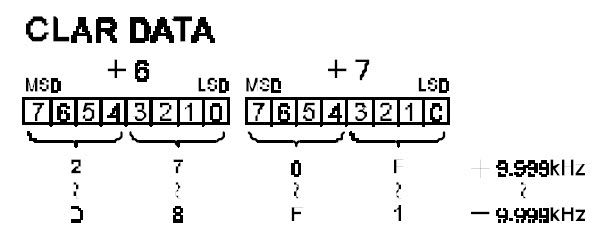
We extract the two bytes and use mask aaaa which interprets as two-s complement binary
and converts to a signed decimal number.
The answermask is : #28:05:02:FF:aaaa answerbytes = 4 because the conversion mask is aaaa
ie: read 28 bytes. Extract 02 bytes starting at byte 05 and convert as 16 bit (4 hex digits) 2s complement.
The number returned to the client as a numeric: -9999 to +9999. (Hz x 10)
The mult, divide, decpoint and units fields control only the displayed value (not the slider)
I set divide to 10 to give -999 to +999 and then set decpoint to 2 to display as -9.99 to + 9.99 kHz.
Sync
I my database, I changed to active = S (auto sync) for the clarifier slider and on/off button.
This makes these controls follow the corresponding status on the radios (as well as the radio following piWebCAT)
See: Indicator controls. 'LED' option
In summary:
Unlike the modern Yaesu radios with easily constructed text commands, the older radios are difficult.
The set and read commands systems are totally different.
The read data has to be extracted from large multi-function data blocks.