5.4 FT920 - Problems encountered
I add the short following section to make the reader aware of differences among these radios
and difficulties with documentation.
Five byte commands
All the CAT manuals refer to a single byte (hex) Opcode and four parameters P1, P2, P3 and P4.
For the FT818 and FT847 they are tabled in the order P1 P2 P3 P4 Opcode.
They must be transmitted in the order: P1 P2 P3 P4 Opcode
For the FT920, they are tabled in the order: Opcode P1 P2 P3 P4
They must be transmitted in the order P4 P3 P2 P1 Opcode
I had huge difficulty with this until I looked at the FT100MKV manual which is much clearer on the subject!
Example: Mode setting command:
The FT818 manual specifies: P1 ** ** ** 07 where 07 is the opcode byte (and * means don't care)
P1 is the mode selecting code, eg: 02 = CW 08 = FM etc
I configure as tu00000007
ie tu 00 00 00 07 where the mode code from the button is mapped into digits t and u.
The bytes are observed on scope decode to go out to the radio in the order:
P1 P2 P3 P4 Opcode ie 02 00 00 00 07 (for CW)
The FT920 manual specifies: 0C P1 ** ** ** where 0C is the Opcode and P1 is the mode code.
(mode codes are totally different from the FT818 and include separate codes for VFO A and VFO B. )
The bytes are actually sent in the order P4 P3 P2 P1 Opcode
and so I must configure as: 000000xx0C (I use xx to allow hex code mapping)
Received frequency data
To read in the 2 x 14 bytes VFO frequency, mode etc we use 00 00 00 03 10 (configured as 0000000310)
The manual says VFO A frequency is in bytes 2 to 5. - In piWebCAT we are zero-indexed and specify 1 to 4.
The answermask is #28:01:04:FF:bbbbbbbb 28 bytes to receive, extract 04 bytes starting at byte 01
The bytes are mapped to the following lower case letters: bbbbbbbb.
(The FF bit mask is unused as it is only for single byte extraction)
I found the download manual to be unclear on the format of the received frequency.
It s actually in binary, ie 14.123450 Mhz is1412345 (to 10Hz) and is received from the radio as 00158CF9.
... I discovered this - not from the manual, but from my Siglent scope's serial data decode facility
I have to use bbbbbbbb to force conversion from binary to decimal. (BCD would use xxxxxxxx)
Note that:
Frequency setting for the FT920 is in BCD (binary coded decimal) .. not binary as frequency read above.
Frequency setting and reading for the FT100MP MkV are both in BCD (The manual is MUCH better)
... all perfectly manageable once you know the correct formats.
FT920 - recall VFO command
This is sent as 00 00 00 P1 05 where, from the manual:
P1 = 00 is VFOA and P1 = 01 is VFOB
I may be missing something here, but my findings were :
P1 = 0 does nothing. P1 = 01 toggles between VFOA and VFO B
This means that I therefore provide a Swap A/B button but no VFO buttons.
The Swap buttons toggles between the two VFO datasets in VFO A.
I do not use the allocated Swap button because this has built inVFO A/B functions which require
configuration access to specifically VFO A and VFO B, and this doesn't appear to be available.
See - IMPORTANT special buttons
FT920 Split on/off:
The manual says send as 00 00 00 P1 01 where P1 = 00 is OFF and P1 = 01 is ON.
My findings were that this switches Tx between VFOA and VFOB
(which is not exactly split on/off !!)
FT920 band switching.
There appears to be no band switching command.
The only way to use the band switching buttons was to configure each with a start frequency for each band as shown:
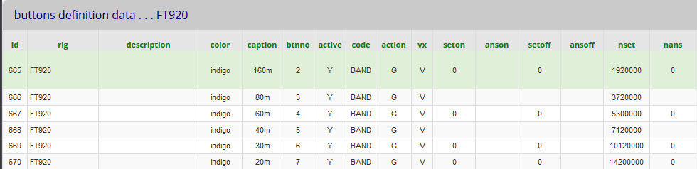
Band buttons are a group and so use fields nset and nans to send data and to match against received data.
We still link to catcodes with code = BAND. The data in field nset is the start frequency for the band (NOT a band code)
catcodes is configured to send the data (eg: 3720000) as a frequency (because, as stated above - there is no band command?)
piWebCAT quickly responds to the frequency change by recognising the new band and changing its tuning scale.
There was a problem here: If you change band by just changing frequency via CAT, no mode change occurs.
The FT920 continues with the operating mode of the the old band and in fact adopts the mode for the new band.
(The radio does in fact store a mode for each band, and if you change bands with the radio's band switches,
the stored mode for the new band is applied )
piWebCAT's solution to the band change problem:
Frequency:
When a band is first selected (in a piWebCAT session), the frequency will be from in the button's table above.
piWebCAT is repetitively reading the FT920 frequency.
At each read, I check the frequency against band limits and then store it for the current band.
So piWebCAT has a record of the latest frequency for each band (modified on the radio or by piWebCAT's tuners.)
If we leave this band and then return to it, piWebCAT examines the nset field.
If this is > 10000, then this indicates that we are configured to change band by frequency (not by band code).
piWebCAT uses the stored latest band frequency to change band rather than the configured start frequency.
Mode
Mode is repetitively read from the radio and is stored by piWebCAT for each band.
I have to lookup the nset value rather than use the nans (which matches received data)
because they are different for the FT920.
On band change, if we are using piWebCAT's stored band frequency as described above,
then we use piWebCAT's stored band mode.
This mode is sent to the radio, 2 seconds after sending the frequency.